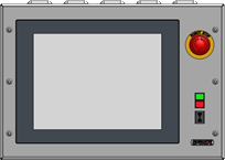
Add Grids - Multi-Assist
|
On some stacking devices, it is possible to apply a grid layout as a means of determining the stacking locations.An unlimited number of grids can be added to the system.This document describes how to create these grids. |
1. Use following tools
|
|
2. Procedure
2.1. Start the IPC
Power on the IPC and start the software.
2.2. Open the configuration menu
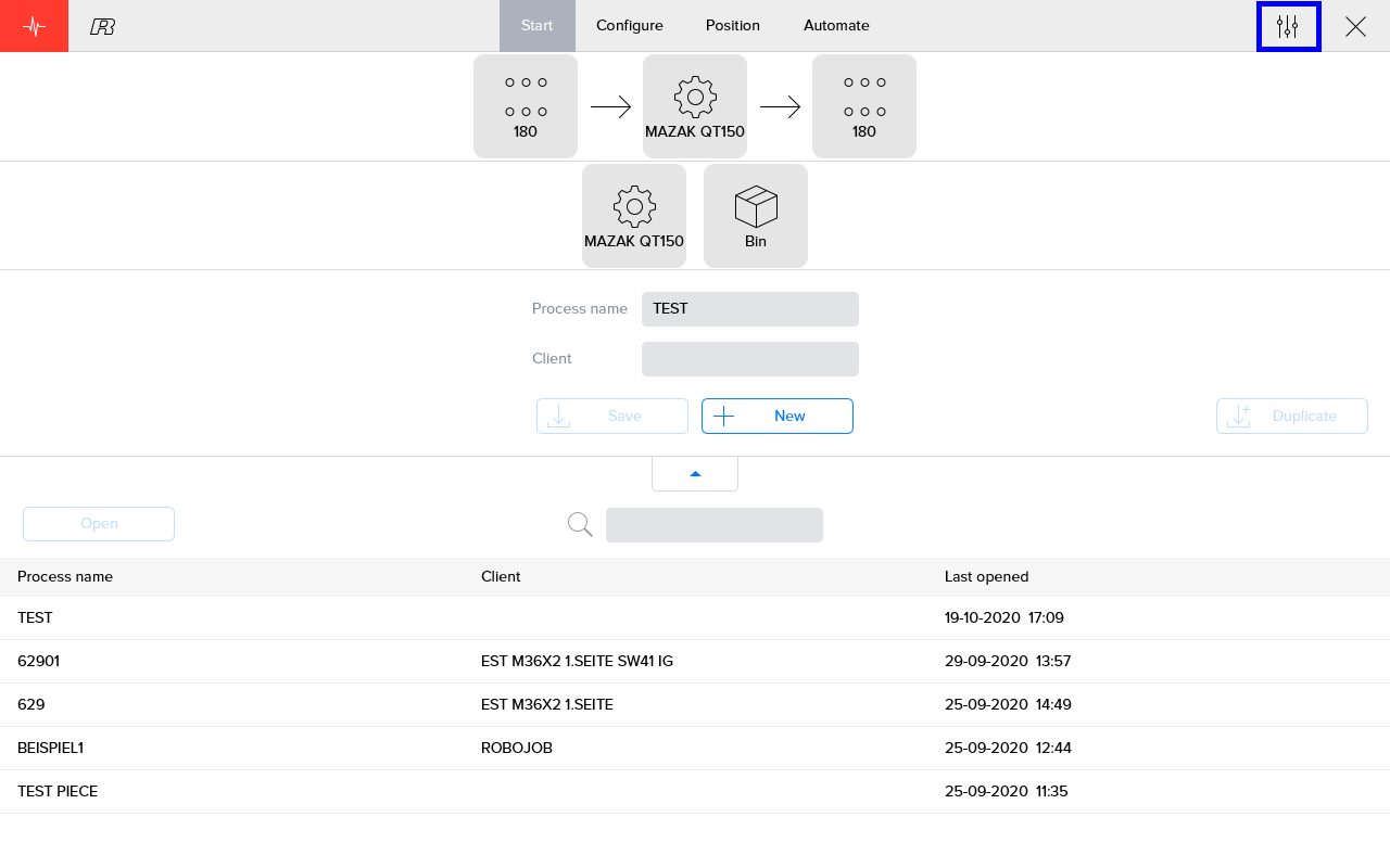
Open Settings by pressing the icon on the top right of the screen.
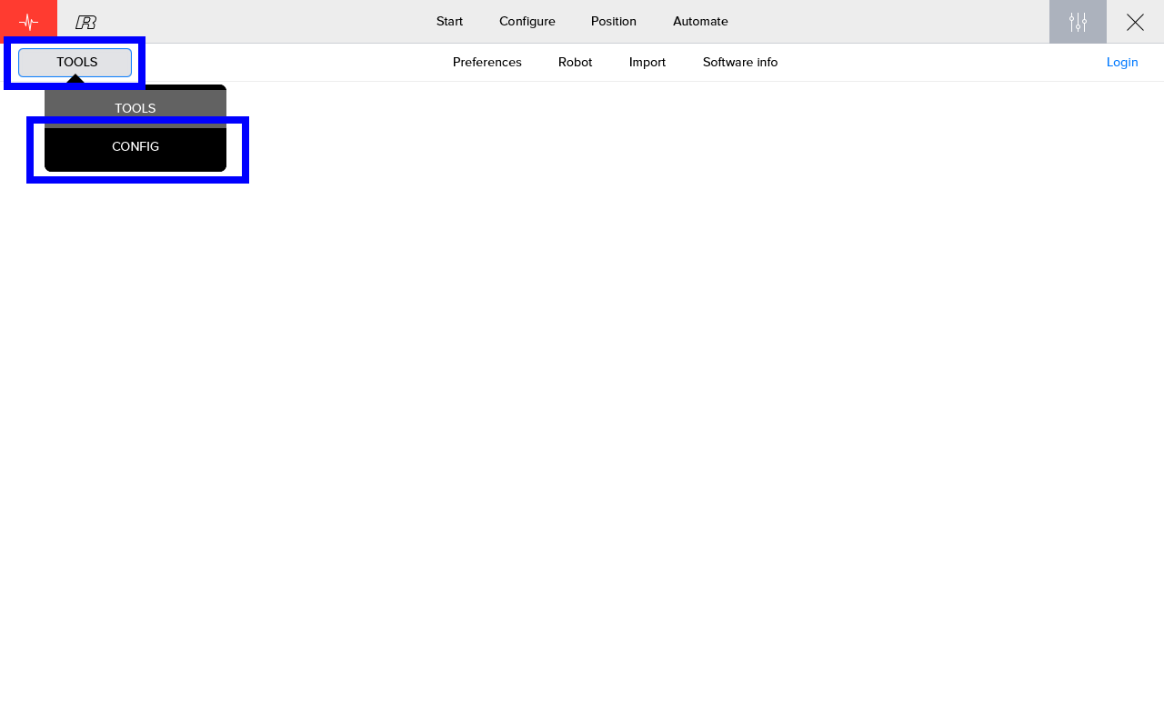
Go to the configuration menu by selecting it on the left.
2.3. Add a new grid
Select the tab 'Grids'.On this tab, press the + sign to create a new grid.

Be sure to give the grid a unique name.
|
It is possible to upload a STL file containing data of the grid, which means the following steps can be skipped.Use the 'Select STL file' button to upload the STL file. 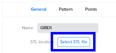
Figure 4. upload STL file
|
2.4. Fill in the general parameters of the grid
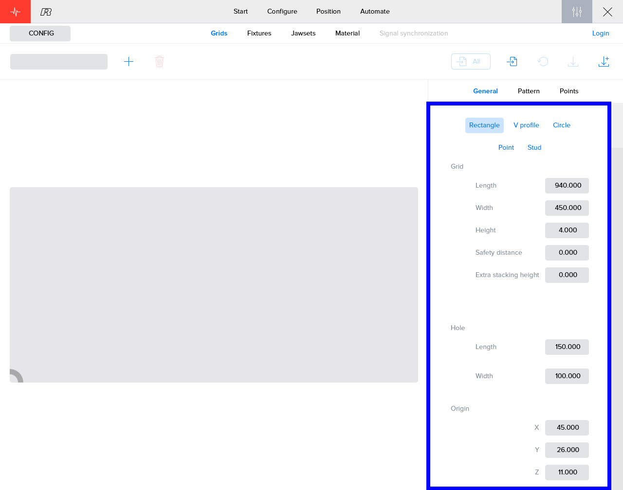
Choose the shape of the alignment features in the grid and fill in the parameters of the grid and alignment features.According to the chosen shape, the parameters of the features will differ.
-
In case of rectangular holes, length and width must be entered.
-
For V-profile the angle must also be specified.
-
For circular holes, the diameter is sufficiant.
-
For point grids, no dimensions are needed.
The last subsection defines the location of the origin of the grid, relative to origin of the device on which the grid is applied to.The origin of the grid is located on the bottom left corner of the grid.The origin of the stacking device is located on the bottom left of the stacking device.The Z value here defines the vertical distance between the stacking device and the bottom of the workpieces in the grid.
The origin can be configured and saved per process.The value set up here is used as the default value.
2.5. Define the grid pattern
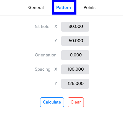
In the previous step we defined the feature in which we want to align the workpieces.The 'Pattern' tab defines where these features are located inside the grid.
First define the location of the first hole relative to the origin of the grid.The orientation field defines a rotation of the features around the Z-axis.The spacing parameter is used to define the distance between origins of the features.
Press the Calculate button to create the pattern.When you want to change the parameters, you must first Clear the previously calculated pattern.
2.6. Alter the grid points
The specific coördinates of every feature, calculated in the previous step are shown here in a list.
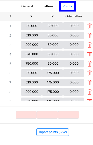
It is possible to add, remove or change the position of specific feature.
The robot will handle the workpieces in the order of the list.It is possible to change this order by dragging the index number of a feature to another position.
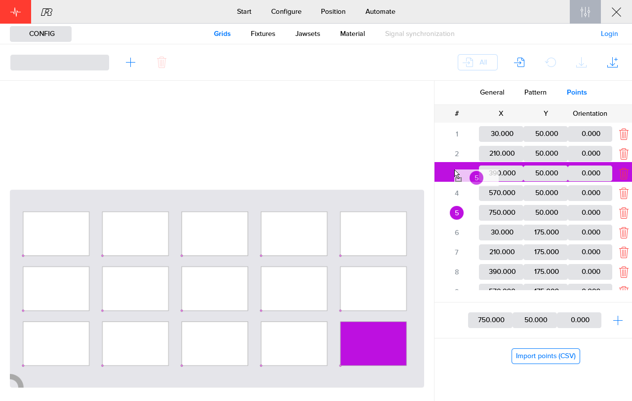
It might be more efficient to create the list of points on a PC.A CSV file, containing the list of points, can be imported using the 'Import points (CSV)' button.
3. How to get further help
Do not hesitate to contact us when you need additional support beyond the documents provided in the RoboJob Service Knowledge Base.
You may contact the RoboJob Service department using following means:
-
Help Center: service.robojob.eu
-
Email: service@robojob.eu
-
Phone: +32 15 70 89 70
We kindly ask you to provide us the following information:
-
Serial number xx-xx-xxx
-
Description of the fault or defective part
-
Exact error code or message
-
What did the robot do
-
What was the robot supposed to do
-
Pictures or videos
You can send this information to us via email.To send large files you may make use of a file transfer service like WeTransfer: robojob.wetransfer.com.
An automatic confirmation will be sent upon receipt of your mail.
