Edit or add custom jaws - Turn-Assist
|
This document describes how to add new (custom) jaws to the software database or how to alter the parameters of existing ones. |
1. Use following tools
|
|
2. Procedure
2.1. Go to robot settings
Start the Turn Assist software on the IPC and click on the settings icon.
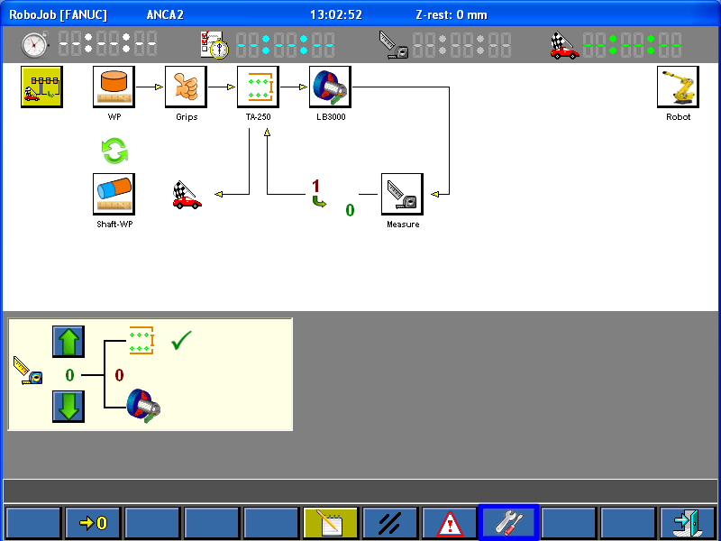
Click on the robot icon.
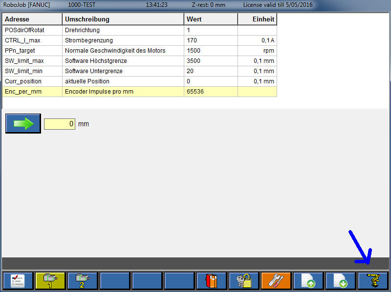
Depending on the installation the robot can have two types of jaws:
-
3 point:Each gripper has 3 jaws that are located at 0°, 120° and 240° around the workpiece.
Typically used for disc workpieces.
-
2 point:Each gripper has 2 jaws or 4 jaws that are located opposite to each other.
Typically used for shaft and block workpieces.
The function keys can be used to create new jaws and copy or delete existing jaws.

2.2. editing 3 point jaws
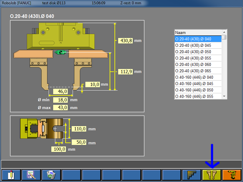
Open the screen to edit the 3 point jaws.
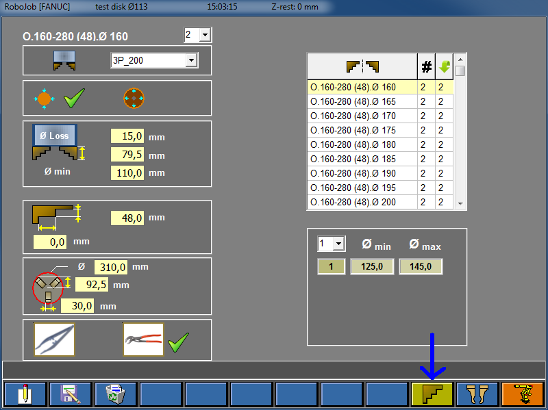
The table on the right side of the screen shows the available jaws for the installation.The first column gives the name of the jaw.The second column indicates how many set are available.A set of jaws contains the amount of jaws needed for one gripper.For 3 point jaws, 1 set has 3 jaws.
Select a jaw in the table to display its properties.
The left side of the screen shows the properties of the selected jaw.These values can be edited.The table below explains the meaning of the fields.
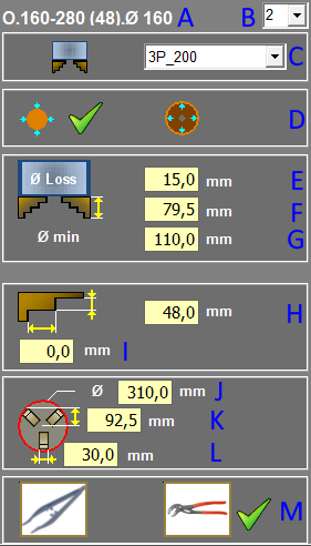
| property | meaning |
|---|---|
|
A |
The name of the jaw. Use a practical and meaningful name when creating a jaw. |
|
B |
The number of sets of this jaw that are available. |
|
C |
The type jaw base on which the jaws are attached. Use the same value for all jaws since you probably won’t be exchanging jaw bases. |
|
D |
External or internal gripping. Click on the icon to change. |
|
E |
The clearance on the stroke. About 3 mm for smaller robots, about 15 mm for larger robots. |
|
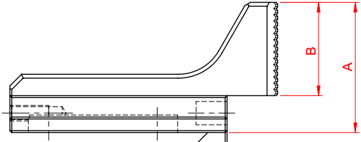
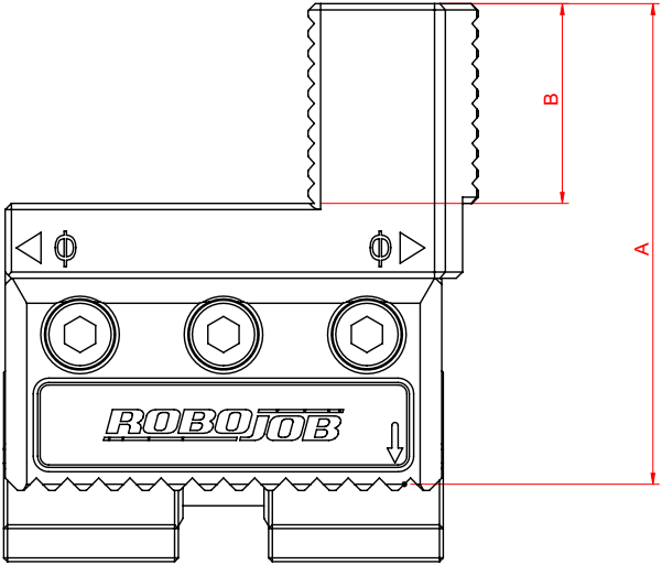
F |
The height of the Jaw. Indicated by A on the pictures below. |
|
G |
The minimum grip diameter. Effective minimum diameter grip without clearance. |
|
H |
The height of the gripper. Height grip section of the jaw. When the gripper has a stop surface, distance to the stop surface. This value is used for calculating the steps. Indicated by B on the pictures below. |
|
I |
Length of the stop surface. Zero if jaw has no stop surface. This value is used for calculating the steps. |
|
J |
The outer circle defined around the jaws. Maximum circumscribed circle of the jaws in the open condition. |
|
K |
Interference value for stacking. Gripper center to outer side jaw in the open position. |
|
L |
The jaw width. |
|
M |
Hard or soft jaws. Click on the icon to change. |
The bottom right side of the screen shows some additional properties of the selected jaw under the jaw selection table.Here you can set the number of steps the jaw has and the minimum and maximum diameter the jaws can grip.On the basis of the information entered, the software will calculate the effective reach this jaw is able to grip for each step.
2.3. Editing 2 point jaws
Open the screen to edit the 2 point jaws.Different types of 2 point jaws exist, so this screen can look different on different installations.
The table on the right side of the screen shows the available jaw for the installation.The name of the jaws are indicated in the table.
Select a jaw in the table to display its properties.
The left side of the screen shows the properties of the selected jaw.These values can be edited.
The meaning of the values can be derived from the drawing.
2.4. Test the adjusted jaws
After adding or adjusting jaws always test at low speed to make sure the new values are correct.
3. How to get further help
Do not hesitate to contact us when you need additional support beyond the documents provided in the RoboJob Service Knowledge Base.
You may contact the RoboJob Service department using following means:
-
Help Center: service.robojob.eu
-
Email: service@robojob.eu
-
Phone: +32 15 70 89 70
We kindly ask you to provide us the following information:
-
Serial number xx-xx-xxx
-
Description of the fault or defective part
-
Exact error code or message
-
What did the robot do
-
What was the robot supposed to do
-
Pictures or videos
You can send this information to us via email.To send large files you may make use of a file transfer service like WeTransfer: robojob.wetransfer.com.
An automatic confirmation will be sent upon receipt of your mail.